
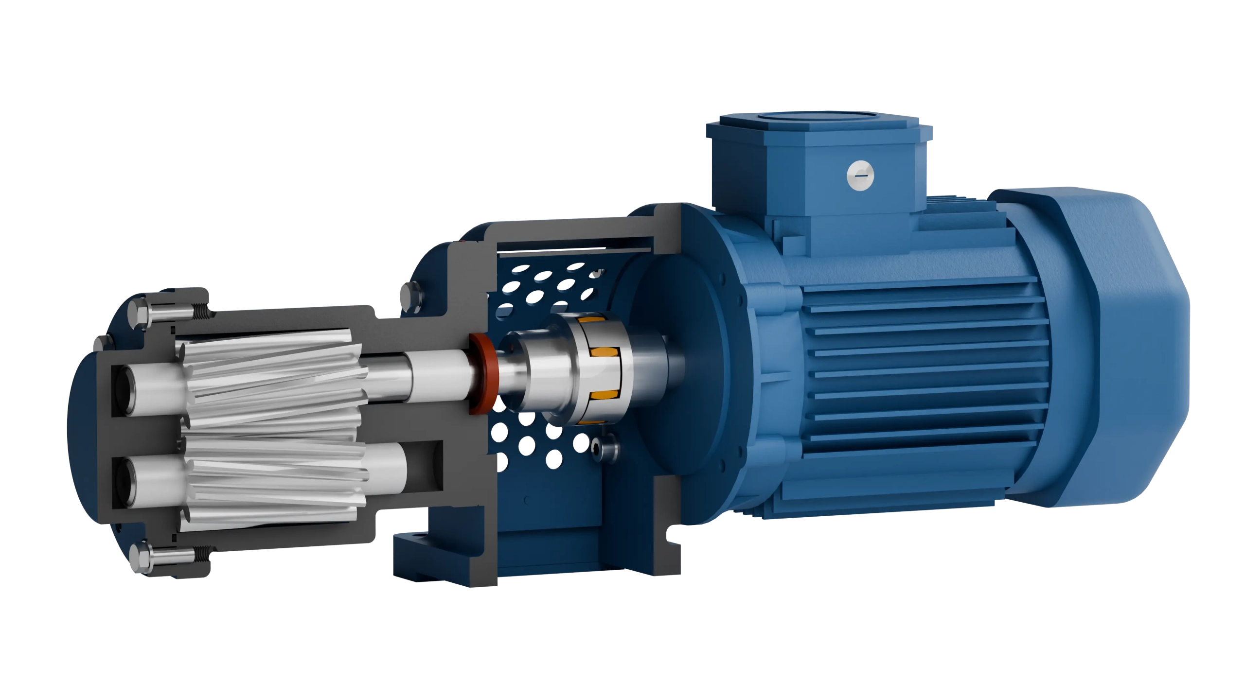
A gear pump consists of surprisingly few parts: two gears, a housing with cover, the bearings for the shafts and a seal that seals the drive shaft to the outside. That it still delivers precisely is due to the tight clearances between these parts and the right choice of materials.
Using the sectional view of the F 590 flange gear pump from Linn-Pumpen, we show which component has which task, which materials are used and where wear occurs during operation.
The components at a glance
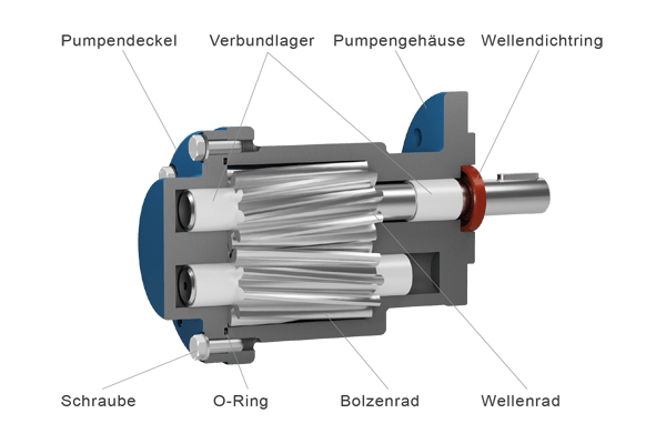
The shaft gear sits firmly on the drive shaft, which protrudes from the housing and is connected to the motor. It drives the idler gear, which runs on its own pin. Both gears sit in the pump housing, which is closed on one side by the pump cover. Composite bearings guide the shafts, an O-ring seals cover and housing against each other, and the shaft seal prevents medium from escaping at the drive shaft.
Gears: the actual pumping element
The two gears determine how much medium is delivered per revolution. The wider the gears and the deeper the tooth gaps, the larger the displacement. At Linn-Pumpen this defines the pump size, for example 219, 328 or 333.
As the sectional view shows, the gears of the F 590 are helical. Several teeth are always in mesh at the same time, so the pump runs more quietly. The medium is carried in the tooth gaps along the outer housing wall, while the tooth mesh in the middle separates the suction and pressure sides.
Housing, cover and clearances
Together with the gears, housing and cover form the pumping chambers. What matters are the clearances between the tooth tips and the housing wall, and between the faces of the gears and the cover. If they are too large, part of the medium flows back to the suction side and the pump delivers less. If they are too small, friction and wear increase. That is why these parts are manufactured to tight tolerances and matched to each other.
The suction and pressure connections are in the housing. To ensure the tooth gaps fill completely, the suction line should be short and sufficiently sized, especially with viscous media.
Bearings and sealing
The shafts run in composite bearings that absorb the radial forces from the delivery pressure. With lubricating media, they are lubricated by the pumped medium itself, one reason why gear pumps should not run dry.
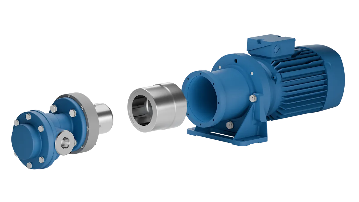
In the standard version, a radial shaft seal seals to the outside. Depending on medium, pressure and temperature, a double radial shaft seal or a mechanical seal can also be used. An alternative is the version with Magnetic coupling: the torque is transmitted contactlessly through a containment can, there is no dynamic shaft seal, and the pump chamber is hermetically sealed from the outside. This also eliminates the typical wear and maintenance point at the shaft seal.
Materials
The materials depend on the pumped medium. Linn-Pumpen offers three pump bases:
| Pump base | Housing | Gear wheels | Typical media |
|---|---|---|---|
| F (cast iron) | Grey cast iron | Case hardened steel | Lubricating, hydraulic and thermal oils |
| E/F (stainless steel) | Stainless steel 1.4571 | Stainless steel 1.4571 | Corrosive media with minimum lubricity |
| E/F-PEEK | Stainless steel 1.4571 | PEEK | Poorly or non lubricating, often water based media |
The cast iron version is the standard for oils. The stainless steel versions are used for corrosive media, the PEEK gears when the medium lubricates little or not at all.
Valve and drive
Because a gear pump keeps delivering even against a closed line, every system needs pressure limitation. On the cast iron versions, a bypass valve can be integrated directly into the pump; this option is not available in stainless steel. Alternatively, a pressure relief valve sits in the bypass of the system.
At Linn-Pumpen, the drive is part of the modular system. The pump is available as a pump head with a free shaft end for a drive provided by the customer, with a mounting foot or as a motor pump with an attached electric motor, if required with a frequency inverter or geared motor.
Where wear occurs
Typical wear parts are the gears, the bearings and the shaft seal. Abrasive particles in the medium enlarge the clearances, and the pump then delivers noticeably less. Dry running damages bearings and tooth flanks, and a leaking shaft seal shows up as drips at the drive shaft. Because gear pumps consist of few parts, these parts can usually be replaced easily.
Frequently Asked Questions
What is the difference between the shaft gear and the idler gear?
The shaft gear sits on the drive shaft and is driven by the motor. The idler gear runs on a pin and is driven by the shaft gear. Together they deliver the medium.
Why does a gear pump need tight clearances?
Medium flows back from the pressure side to the suction side through the clearances. The tighter they are, the less is lost and the more precisely the flow rate matches the speed.
Which parts wear first?
Often the shaft seal, and with abrasive media also gears and bearings. With a clean, lubricating medium and a suitable speed, these parts last considerably longer.
Conclusion
Gears, housing, bearings and seal: a gear pump needs nothing more. How well it works is decided by the clearances, the materials and the sealing. We will be glad to work out which combination suits your medium based on your operating data.

