How does an external gear pump work?
An external gear pump, that is, a gear pump with external teeth, is a rotary positive-displacement pump. Two externally toothed gears mesh with each other and rotate in opposite directions. On the suction side, the gaps between the teeth open; the fluid flows in and is transported through these gaps along the housing wall to the discharge side. There, the teeth mesh again and displace the fluid into the discharge line. This process occurs continuously, resulting in a flow rate with virtually no pulsation.
The theoretical flow rate is calculated from the displacement and the rotational speed. Flow rate in liters per minute equals displacement in cubic centimeters per revolution multiplied by rotational speed in revolutions per minute, divided by 1,000. A pump with a displacement of 20 cm³/rev therefore delivers approximately 29 l/min at 1,450 min⁻¹. The actual flow rate is lower than this because, as the differential pressure increases, a portion of the fluid flows back through the clearance losses.
This is precisely where the practical difference from a centrifugal pump lies. A centrifugal pump experiences a significant drop in flow rate as back pressure in the flow increases. A gear pump largely maintains its flow rate even as pressure rises, and it can also handle viscous fluids where a centrifugal pump reaches its limits.
Where are gear pumps used?
Gear pumps from Linn-Pumpen are used wherever a fluid needs to be delivered evenly, in metered quantities, and against pressure. Gear pumps for oil are primarily used for lubricating oils, hydraulic oils, and heat transfer oils. Typical applications include supplying lubricating oil to machines and large bearings, operating hydraulic power units, transferring fluid from drums and IBCs, circulating heat transfer oils, supplying cooling and lubrication circuits, and metering in process and control loops.
Because the flow rate is proportional to the speed, a gear pump can be used for very precise metering. When combined with a variable-frequency drive or the “i” model with an integrated drive controller, the pump becomes a controllable metering unit.
Six Questions Before Interpretation
Medium
The key factor is whether the medium is lubricating. Oils, heat transfer fluids, and lubricants are not a concern. For media with little or no lubricating properties—such as solvents, water, or low-viscosity chemicals—the material and rotational speed must be adjusted, usually by using PEEK gears.
Viscosity
The permissible viscosity is directly dependent on the rotational speed. At 1,450 min⁻¹, the permissible viscosity is 250 mm²/s for sizes F 1 and F 2, and 350 mm²/s for sizes F 3 through F 5. If the speed is reduced, the permissible viscosity increases significantly—to approximately 1,500 mm²/s at 1,000 min⁻¹ and to approximately 2,500 mm²/s at 700 min⁻¹. With a G-series gearmotor configuration, viscosities of up to 20,000 mm²/s are possible at low speeds; typical values are 6,000 mm²/s at approximately 450 min⁻¹, 10,000 mm²/s at 300 min⁻¹, and 20,000 mm²/s at 200 min⁻¹. For high viscosity, a feed operation must be provided.
Pressure
The maximum allowable pressure depends on the size and, depending on the model, is 10, 50, 70, or 100 bar. For motor-driven pumps, the selected motor power also limits the allowable pressure. For this reason, each motor-driven pump is designed for a specific operating point and not for the maximum value indicated on the pump head.
Delivery rate
Sizes F 1 through F 5 cover flow rates ranging from 0.43 to 86.8 cm³/rev, which corresponds to a range of approximately 0.6 to 124 l/min at 1450 min⁻¹. The maximum flow rate and maximum pressure are two separate limits and not a common operating point; the flow rate decreases as the pressure increases.
Temperature and Seals
The medium temperature determines the type of seal. NBR can be used up to 60 °C, FPM and FKM up to 150 °C, and PTFE up to 200 °C. A mechanical seal is permissible up to 150 °C and 15 bar inlet pressure; a graphite gland packing is permissible up to 200 °C. If no dynamic shaft seal is to be used at all, the FOM-MG Magnetic Coupling Model the right choice.
Drive
If the pump is to be integrated into an existing machine, the flanged pump with a free shaft end is the correct choice. If it is to be delivered ready for operation, the Electric gear pumps the right choice. For control applications, there is the i model with an integrated drive; for high-viscosity media, there is the G gearmotor model.
Gear Pump Series and Drives in Detail
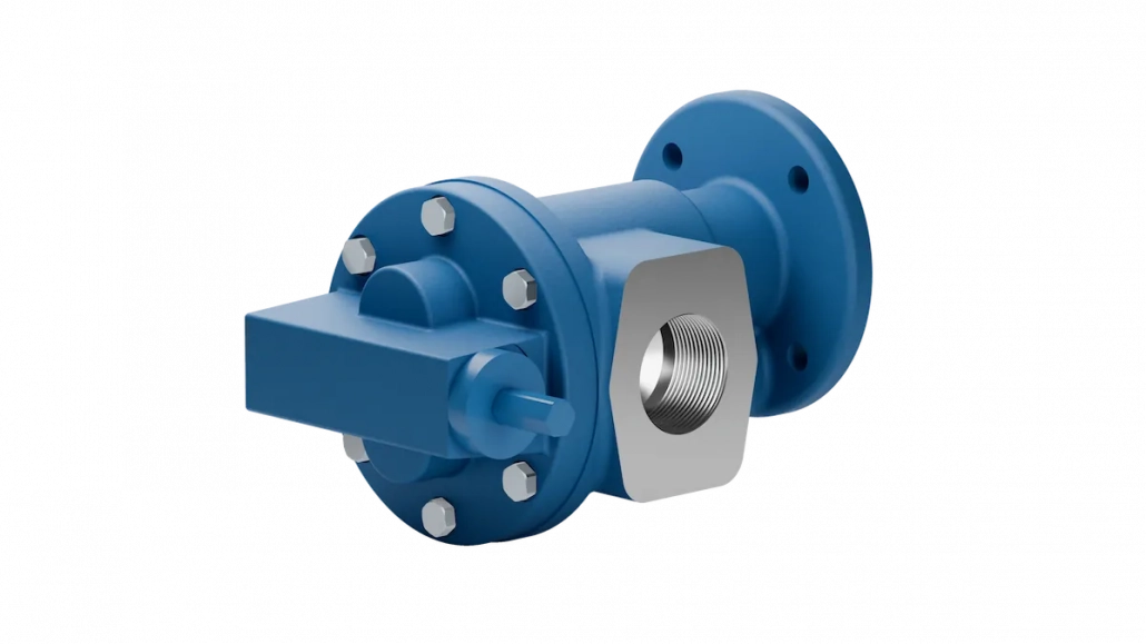
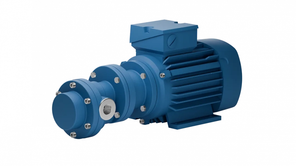
Linn-Pumpen offers three basic pump series: F in gray cast iron, E/F in stainless steel, and E/F-PEEK in stainless steel with PEEK gears. Within each pump series, every model is composed of three additional components: size, body and motor configuration, and features. Size and body and motor configuration are separate categories. The same size 333 is available as FLM 333, FKM 333, or FOM 333, depending on the required motor power.
- F Flanged pump with exposed shaft end for customer-supplied drive
- D The same pump head with mounting base
- FLM Electric power unit with BoWex curved-tooth coupling and aluminum pump bracket, 0.12 to 1.5 kW, only up to and including size 3
- FKM Electric power unit with ROTEX claw coupling and aluminum bracket, 0.55 to 1.5 kW, also for sizes 3 and 5
- FOM Electric power unit with ROTEX coupling and KTR pump mount, 2.2 to 18.5 kW
- FAM Tank-mounted, pump head inside the tank, external motor, 0.25 to 18.5 kW
- MG equipment Magnetic coupling, without dynamic shaft seal, guided in the FOM design as FOM MG
- Equipment G Helical gear motor for high-viscosity fluids at low speeds, typically with FKM and FOM seals, designated as G/FKM or G/FOM
- Equipment i Integrated frequency converter; speed and flow rate adjustable; designated as FLMi, FKMi, or FOMi immediately after the model designation
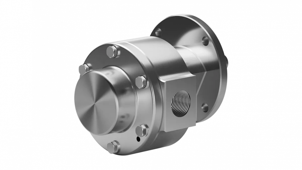
- E/F, E/D, E/FLM, E/FKM, E/FOM and E/FAM Stainless steel version in 1.4571, with a free shaft end or with a motor
- PEEK variants Stainless steel models for media with little or no lubrication
- Equipment U Integrated relief valve, available in cast metal as FU, DU, FLMU, FKMU, FOMU, and FAMU. The U version is not available in stainless steel.
- LZ and LZGM Separate series outside this modular system, low-speed operation, maximum 500 min⁻¹, 210 and 320 cm³/rev. LZ without drive, LZGM with drive
Materials: Cast metal, stainless steel, and PEEK
The standard version features a housing made of EN-GJL-250, with shafts and gears made of 16MnCr5. A special version made of GGG40 ductile iron is available. This combination is the right choice for oils, heat transfer fluids, and all well-lubricating media.
The Stainless Steel Version It uses a housing, cover, and shafts made of 1.4571. It is designed for corrosive media that still provide sufficient lubrication. PEEK gears are used when the medium provides little or no lubrication, such as with solvents or low-viscosity chemicals. In this case, the design is always tailored to the specific medium.
An important note: We do not currently offer ATEX-compliant models or hygienic or food-grade pump models. We would be happy to discuss with you on a case-by-case basis how stainless steel and PEEK can meet the requirements of your specific medium.
Operating Limits of Gear Pumps
Gear pumps are self-priming but are not protected against dry running. Dry running will damage the pump within a short time and is not permitted in any model series. Solids and abrasive particles must not be present in the pumped fluid; fine pre-filtration is recommended.
The integrated bypass valve is a safety valve, not a continuous pressure regulator. It protects the pump in the event of a brief pressure surge; continuous bypass flow through the valve is not intended. For continuous pressure limitation, please use an external DB Series Pressure Relief Valve one.
Here's how a model number is put together
Pump base, size, design and motor type, and features. Every model is based on these four components.
Example: E/FLMi 328 refers to a stainless steel pump in the FLM design with a motor, size 328, and an integrated frequency converter. The configuration codes mean: U for relief valve, MG for magnetic coupling in the FOM design, i for frequency converter immediately following the design code, and G for gearmotor as a prefix. The FLMU 219 is also formed in this way, from size 219, the FLM model, and the relief valve. It is listed as a separate product because this combination has proven itself in practice; technically, it is not a separate series.
All specifications are approximate. The technical design based on the medium, viscosity, temperature, flow rate, and pressure is decisive.