
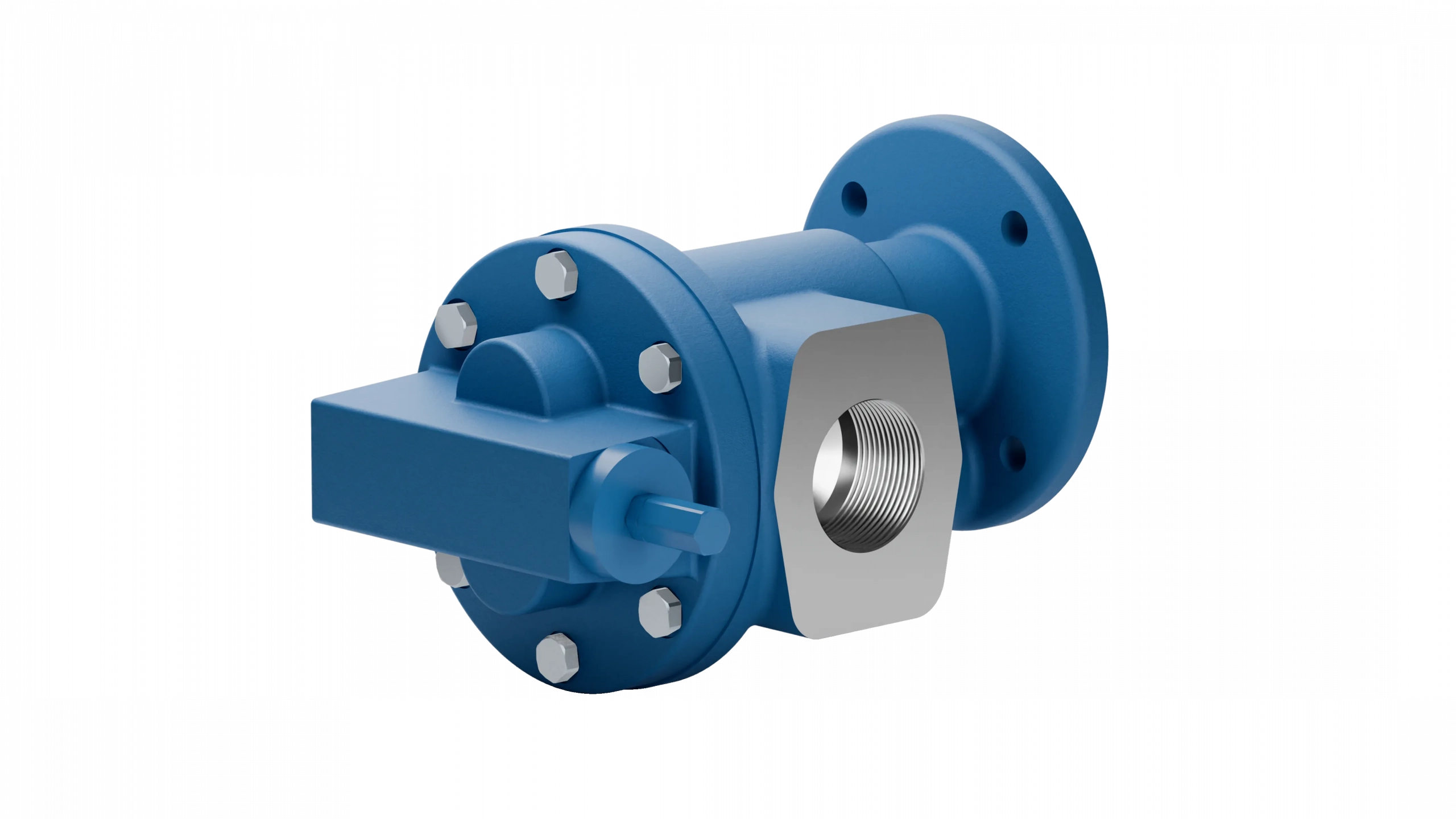
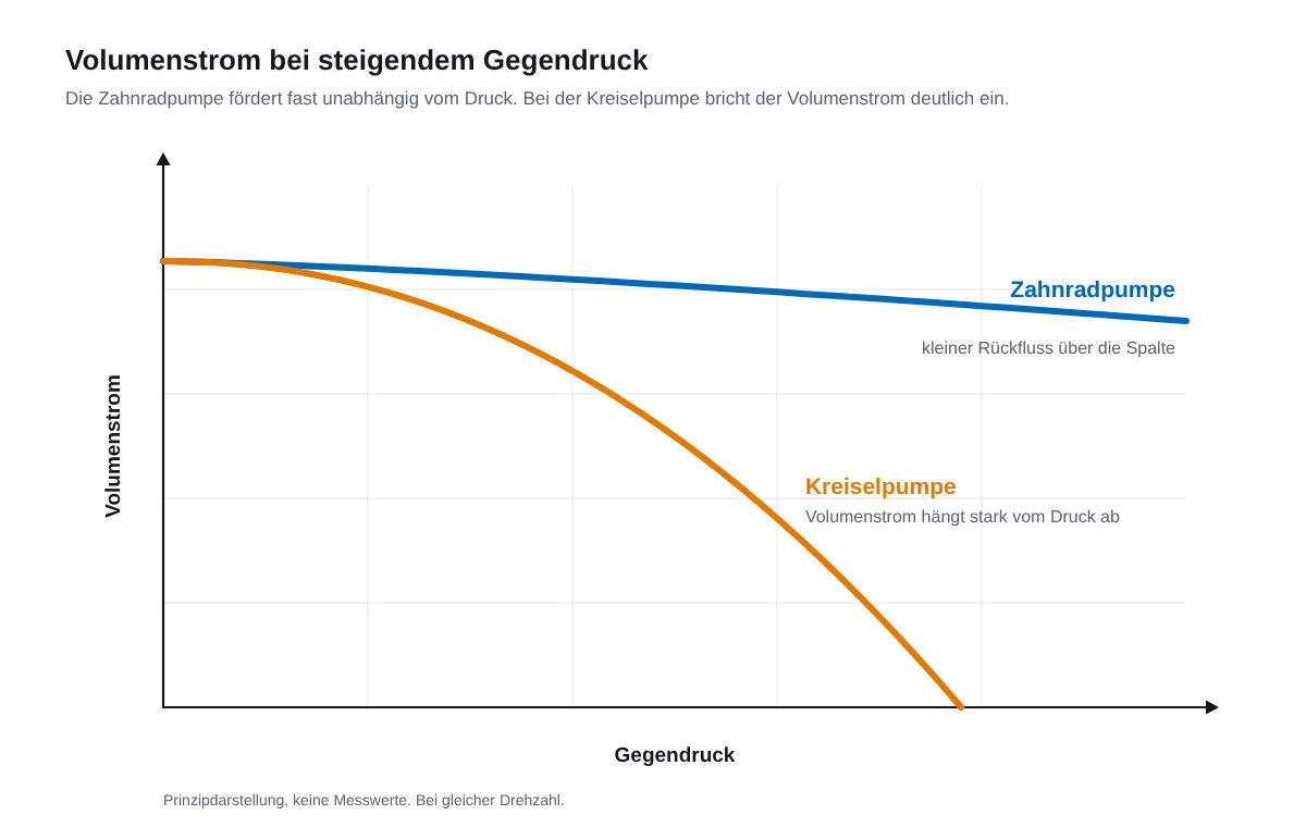
A gear pump is a rotary positive displacement pump: two meshing gears trap the pumped medium in their tooth gaps and push it from the suction side to the pressure side. A fixed volume is delivered with every revolution. That is exactly what sets it apart from a centrifugal pump, which accelerates the liquid through the flow and whose flow rate depends heavily on the back pressure.
In this article you will see how a gear pump delivers step by step, why it is self priming, why it always needs pressure limitation and which tasks it is particularly suited for.
How a gear pump delivers
The most common design is the external gear pump. One gear sits on the drive shaft and drives the second gear; both turn in opposite directions in a housing with tight tolerances. On the suction side the teeth separate. The tooth gaps open, a vacuum is created and the medium flows in from the suction line.
The gears then carry the medium in their gaps along the outer housing wall. Nothing is pumped through the middle between the gears. That is where the teeth mesh and seal the suction side against the pressure side. On the pressure side, the teeth come together again, the gaps become smaller and the medium is displaced into the pressure line.
Besides the external gear pump there is the internal gear pump, in which a pinion runs inside an internally toothed ring gear. Both work on the same principle. How they differ in design, smooth running and maintenance is explained in the article Internal or external gear pump.
What the displacement principle means in practice
Because every revolution delivers a fixed volume, the flow rate depends almost only on the speed. Put simply: flow rate equals volume per revolution times speed, minus a small share that flows back through the clearances between gears and housing. This backflow is larger with thin media and high pressure, and smaller with viscous media. The flow rate can therefore be set easily via the speed, for example with a frequency inverter.
For the same reason, a gear pump is self priming. It can draw medium from a lower tank if the suction line is short, sufficiently sized and leak tight. How high it can lift depends on the medium, viscosity and temperature. With viscous oils, the achievable suction lift decreases.
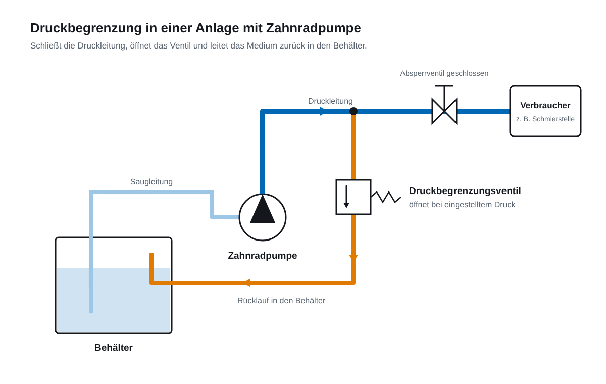
The flip side: a gear pump keeps delivering as long as it is driven, even against a closed line. The pressure then rises until the pump, line or drive is damaged. Every system with a gear pump therefore needs pressure limitation, either as a bypass valve directly on the pump or as a pressure relief valve in the system.
What gear pumps are used for
Gear pumps play to their strengths wherever a defined flow rate is required and the medium has a certain viscosity. Typical uses are the oil supply of machines and gearboxes, the lubrication circuit, thermal oil in temperature control units, transfer from drums and IBCs, and metering tasks where the quantity is controlled via the speed.
They reach their limits with media containing solids or abrasive particles, because these wear the tight clearances. Very thin, non lubricating media such as water require suitable materials, for example stainless steel with PEEK gears.
Gear pumps from Linn-Pumpen
Since the 1960s, Linn-Pumpen has been manufacturing its own Gear pumps of the external gear pump type. The range is a modular system: the pump base is available in grey cast iron, in stainless steel 1.4571 and in stainless steel with PEEK gears. Depending on pump size, design and motor type and equipment, this results in the right version, from the pump head with a free shaft end to the motor pump with frequency inverter. The range covers flow rates up to 124 l/min at 1,450 min-1 and viscosities from 1.4 to approx. 20,000 mm²/s.
Frequently Asked Questions
How does a gear pump work, simply explained?
Two gears turn against each other. Where the teeth separate, the gaps fill with medium. The gears carry it along the outside of the housing to the other side, where the teeth mesh again and push the medium out.
Can a gear pump run dry?
No. Gears, bearings and shaft seal are lubricated and cooled by the pumped medium. If the pump runs dry for a longer time, it wears quickly. Before the first start, the pump chamber should therefore be filled with medium.
How is the flow rate controlled?
Via the speed. Half the speed means roughly half the flow rate. In practice this is usually done with a frequency inverter, and with very viscous media with a slow running geared motor.
Which media are suitable?
Above all oils, lubricants, thermal oils and many viscous liquids. For corrosive or poorly lubricating media, stainless steel versions and PEEK gears are an option. Media containing solids are not suitable for gear pumps.
Conclusion
A gear pump delivers a fixed volume per revolution, is self priming and handles viscous media well. It needs a clean, ideally lubricating medium and always pressure limitation. Which version fits depends on the medium, viscosity, temperature, pressure and flow rate. Send us these operating data and we will size the right gear pump.
