
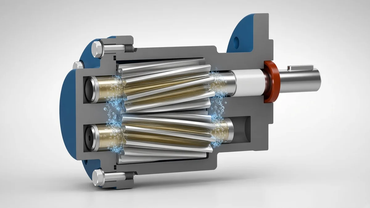
A pump suddenly starts to run loudly, hum or vibrate, and the flow rate decreases. Often behind these signs is cavitation. The cause is almost never in the pump itself, but on the suction side of the system. Anyone who is familiar with it can avoid cavitation already during design.
This guide explains how cavitation occurs, why gear pumps can also be affected, and which guidelines and design rules Linn pumps use for the suction side.
What happens in cavitation in the pump
Every liquid has a vapor pressure. If the pressure at a point falls below this value, the liquid begins to vaporize there, even though it is not heated. Small vapor bubbles form. In a pump, this occurs where the pressure is lowest, that is at the inlet on the suction side.
The bubbles migrate with the medium to areas of higher pressure. There, the vapor condenses instantly and the bubbles collapse in on themselves. These implosions generate locally strong pressure impulses. If they occur near a surface, they gradually wear away material. At the same time, the vapor bubbles take up space that is actually intended for the transporting medium.
What is different from this is air or gas in the medium. Solubilized gases can escape when the pressure decreases, and leaky suction lines attract air. The consequences are similar; the remedy begins on the suction side in both cases.
Why gear pumps can also be affected
Cavitation is often associated with centrifugal pumps. In these systems, the NPSH value describes how much pressure at the inlet must be present. To prevent cavitation from occurring, the NPSH available in the system must be above the required pump value. More information about this program can be found on the page. Centrifugal pumps.
A gear pump works according to the displacement principle. Two gears mesh in the housing and convey the medium through the tooth gaps from the suction side to the pressure side. On the suction side, the tooth gaps open and have to fill completely in a short time. The contribution explains in detail how the conveying principle works in detail. What is a gear pump.
If the medium does not flow quickly enough, the gaps in the teeth are only partially filled and a vacuum is created. This happens when the suction line has too much resistance, a pre-filter is too small or dirty, the suction height is too high or the medium is too viscous for the selected speed. If the pressure falls below the vapor pressure of the medium, cavitation occurs. Although the gear pump is self-priming, this does not mean unlimited suction height or the ability to run dry.
Incomplete filling is not the same as cavitation
Both effects are related, but are not the same thing. In an incomplete filling, too little medium reaches the gaps between the teeth. The pump then delivers less than its speed would allow. Cavitation only occurs when the pressure falls below the vapor pressure of the medium, forming steam bubbles that suddenly collapse in the area with higher pressure.
A pump can therefore be filled incompletely without cavitating, for example when it sucks air through an leaky suction line or when dissolved gases are released. Differentiation is important to remedy this problem. Higher pressure at the pump inlet helps against cavitation, while a dense suction line prevents suction of air.
Typical signs of cavitation
The noise is most noticeable. A cavitational pump sounds rough, roaring or gurgling, as if it were pumping gravel. In addition, there is often vibration and a rougher running. The flow rate decreases because part of the flow volume is filled with steam instead of the medium, and the pressure on the pressure side can fluctuate.
If the condition persists for longer, damage will occur. Typical signs are jagged, washed-out areas on the tooth flanks, housings, or caps. The bearing and shaft seal are additionally subjected to strain due to the vibrations. If such signs appear, it is worth taking a look at the suction side and the operating data first before replacing parts.
The most common causes are on the suction side
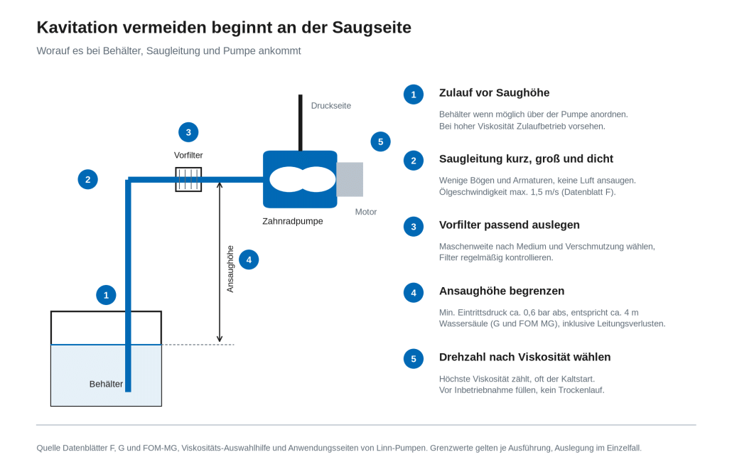
The pump can only pump as much medium as flows in from the suction side. Any resistance before the pump inlet further reduces the pressure there. This includes long or too narrow suction hoses, many bends, fittings, and too small or dirty prefilters. If the container is located below the pump, the suction height is added.
For the G gear motor design and the FOM MG magnetic coupling gear pump, Linn Pumps specifies a permissible minimum inlet pressure at the suction side of approximately 0.6 bar absolute. This results in a guideline value of approximately 4 m water column for the suction height for these two designs. This is not a general limit for all gear pump designs. Other series, media, and operating conditions can lead to different values. The resistances of the suction line are also taken into account. The more pressure is lost in the line, the less suction height remains.
The flow speed also plays a role. The performance charts in the data sheet for the gear flange pump F apply to an oil speed of a maximum of 1.5 m/s on the suction side and a maximum of 4.5 m/s on the pressure side. The suction line is therefore usually dimensioned larger than the pressure line.
In addition, there are the properties of the medium. With increasing temperature, the vapor pressure increases; the liquid thus vaporizes already at higher pressure. Easily volatile media such as solvents are particularly sensitive. Linn pumps have a side Solvents It is expressly recommended to avoid steam and gas components. In the case of viscous media, the resistance in the suction line increases, and the gaps between the teeth need more time to fill up.
Adjusting the rotational speed and viscosity correctly
In a gear pump, the rotational speed is an important factor against incomplete filling, but not always the most important one. Even a too small or dirty pre-filter can lower the pressure at the pump inlet so much that cavitation is favored. The more viscous the medium, the slower the pump must run so that the medium can fill the tooth gaps in time. Linn pumps provide guidelines for this. With a four-pole motor at approximately 1,450 rpm to approximately 350 mm²/s, with a six-pole motor at approximately 950 rpm to approximately 1,500 mm²/s, and with an eight-pole motor at approximately 700 rpm to approximately 2,500 mm²/s. For the smaller F1 and F2 models, the guideline is 1,450 rpm at up to 250 mm²/s.
When designing a lubricant, the highest viscosity that occurs during operation is taken into account. This is often the cold start, when an oil is not yet at operating temperature. The contribution shows how viscosity and temperature are related in oils. Gear pump for oil.
For highly viscous, lubricating media up to 20,000 mm²/s, there is the Gear motor version G With a spur gear drive motor and low pump rotation speeds. For them, Linn recommends using a high-viscosity pump with a high-flow inlet and a short, large-dimensioned suction line. The separate series LZ and LZGM It is intended for viscous media. According to Linn, its low rotational speeds reduce shear, heating, and cavitation tendencies.
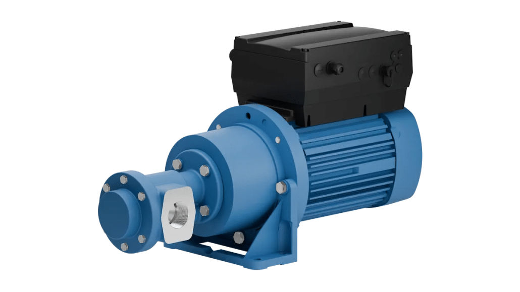
If the viscosity or flow rate in operation changes, adjust the pump’s speed via the speed control, for example with a frequency converter. Version i It already comes integrated with the motor. However, a frequency converter does not increase the pump's limits. It only helps to stay within the allowable range.
Symptoms, possible causes, and testing steps
The following overview helps with initial narrowing down. It does not replace an examination of the system, but it does show where you should start first.
| Symptoms | Possible cause | Testing step |
|---|---|---|
| Loud, rumbling or hissing noise, vibrations | Pressure at the pump inlet falls below the vapor pressure, the pump cavitates | Check the suction side: suction height, length and nominal diameter of the suction line, bends, valves and pre-filters |
| Funding amount lower than expected | Incomplete filling of the tooth gaps; speed too high for the viscosity | Compare viscosity at operating temperature and during cold start with the rotational speed guidelines |
| The amount of funding decreases over time | Pre-filter too small or increasingly contaminated | Check and clean the pre-filter for size and contamination |
| Slower running, fluctuating pressure on the pressure side | Air is drawn in via a leaky suction line, or dissolved gases are gassed out. | Check the suction hose for tightness |
| Problems mainly with cold start | Highest viscosity as long as the medium is cold | Set the rotational speed and suction line to the viscosity at cold start, check the inlet operation |
| Problems at higher temperatures or with solvents | Higher vapor pressure; the medium vaporizes already at higher pressure | Check media temperature and vapor pressure; increase pressure at the pump inlet, for example by supplying air |
| The pump does not pump after commissioning | Pump not filled with medium; suction height too high | Fill the pump with medium before starting up, avoid dry running, and check the suction height |
| Scaly, washed-off areas on the tooth flanks, housings or covers | Longer-lasting cavitation | Fix the cause on the suction side before replacing parts |
This is how you avoid cavitation in the system
Most measures can be implemented during planning and cost little at that point. They are often more complex afterwards.
- If possible, arrange the container above the pump so that the medium flows. In the case of high viscosity, flow-through operation is the rule.
- Sump line short, sufficiently large and flow-friendly, with few bends and fittings.
- Seal the suction hose tightly to prevent any air from being drawn in.
- Provide a pre-filter and arrange it sufficiently large; choose the mesh size according to the medium and contamination; and regularly check and clean the filter.
- Select the speed appropriate to the highest viscosity encountered.
- Fill the pump with the medium before starting up. Running dry is not allowed.
The pressure side also includes a pressure limit in the system, because a gear pump also continues to pump even when the outlet is closed. Suitable solutions can be found on the page. Valves. The page shows how an oil supply system with pre-filters and a bypass valve can be constructed. lubrication circuit.
Properly setting up gear pumps in practice
When designing a gear pump, not only flow volume and pressure are important. For the pump to operate without cavitation, the suction side must be included from the outset. In practice, this approach has proven effective.
- Based on the most unfavorable operating condition. This is usually the highest viscosity at cold start, while for volatile media the highest medium temperature is reached.
- Calculate the suction side: Suction height or inlet as well as the losses in the suction line, bends, fittings and pre-filters. The pressure at the pump inlet must remain above the minimum inlet pressure of the selected design and be at a distance above the vapor pressure of the medium.
- Choose the pre-filter to be sufficiently large and take its pressure loss into account even in a contaminated state, not just in a clean state.
- Dimension the suction line according to the flow rate. The power tables for the gear-flange pump F apply to a maximum of 1.5 m/s on the suction side.
- Set the rotational speed and size of the pump together. If the viscosity allows only a low rotational speed, the desired flow rate is achieved through the size of the pump, not through a higher rotational speed.
- Plan for continuous operation with high viscosity.
- Use a frequency converter to stay within the allowable range; he does not shift the pump’s limits.
We need this data for the design
Whether cavitation is threatening can be well assessed with a few details about the suction side and the medium. Keep the following data as ready as possible.
- Medium, preferably with safety data sheet
- Viscosity at operating temperature and during cold start
- minimum and maximum media temperature
- desired flow rate in l/min and pressure on the pressure side
- Position of the pump, i.e. inlet or suction height
- Length and nominal diameter of the suction line as well as filters and fittings therein
Don't you know all the values? Please provide the information that is known to you. We will clarify the missing points together with you.
Request pump design
Send us your operational data via the form Request pump design or call us at 02355 9029-29. We will check the suction side, medium and speed and will contact you with a technically justified proposal.
Frequently asked questions about cavitation in pumps
What is cavitation in a pump?
Cavitation is the formation of vapor bubbles when the pressure in the medium falls below the vapor pressure. The bubbles collapse suddenly in areas of higher pressure. This causes noise, vibrations, loss of power, and, in the long run, material erosion.
How do I know that my pump is cavitating?
Typical symptoms are a roaring or hissing noise, vibrations, a decreasing flow rate, and fluctuating pressure. With prolonged cavitation, jagged areas appear on the tooth flanks or housing.
Can a gear pump cavitate?
Yes. If the gaps in the suction side are not completely filled, a vacuum is created. If the pressure falls below the vapor pressure of the medium, the pump will vibrate. Common reasons are an excessively high suction height, an unfavorable suction line, a too small or dirty prefilter, or a too high speed for the viscosity of the medium. However, not every incomplete filling is cavitation; even aspirated air can be the cause.
How high can a gear pump suck in?
This depends on the design, medium and suction line; there is no general limit for all gear pumps. For the G and FOM MG models, Linn-Pumpen specifies a minimum inlet pressure of approximately 0.6 bar absolute, which corresponds to a guideline of approximately 4 m water column. The losses in the suction line can be deducted from this.
